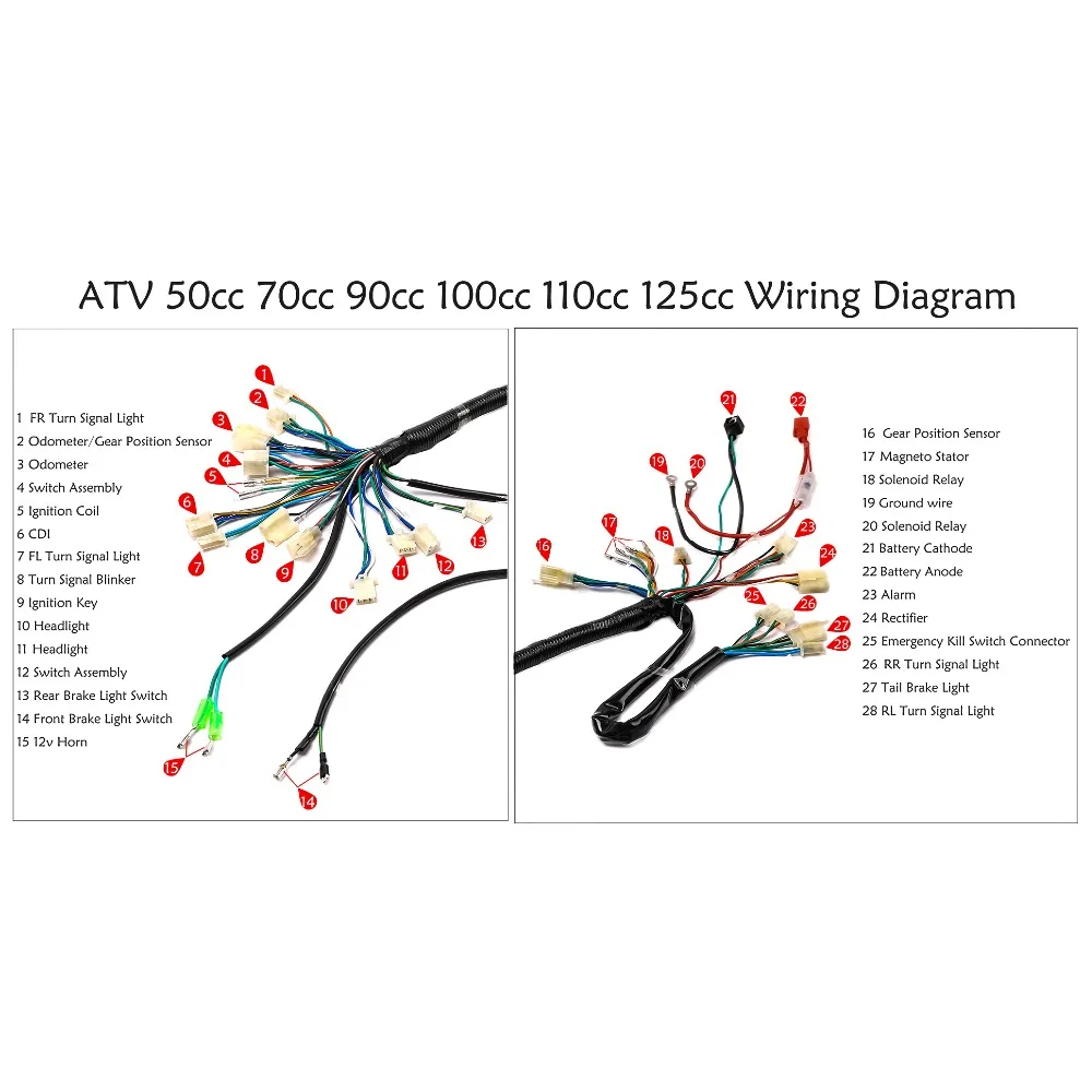
110Cc Atv Wiring Diagram – 110 quad wiring diagram, 110cc atv cdi wiring diagram, 110cc atv electrical diagram, Every electric arrangement is made up of various unique components Each component should be set and connected with different parts in particular way If not, the arrangement won’t work as it should be Share Posted I have put all of the wiring diagrams into a single PDF file to make life a little more simple and for some reason there was a 97 kb limit on zip files this time and it was 30 mb in my first post Here is what is included Wiring Diagrams 4 Pin CDI Wiring Diagram Chinese ATVjpg0cc Atv Wiring Diagram Cheap electric cdi, Buy Quality cc atv directly from China atv quad Key switch, Estart/kill Cluster switch/remote Choke, Easy to read Wiring Diagram Buy CC CC ATV QUAD FULL ELECTRICS CDI COIL RECTIFIER WIRING HARNESS WIRE LOOM Looms 10, Easy to read Wiring Diagram

Cdi Capacitor Discharge Ignition Circuit Demo Ignition Coil Capacitor Circuit Diagram
Cdi kill switch diagram
Cdi kill switch diagram- Gy6 Cdi Wiring Diagram Gy6 50cc 125cc 150cc atv taotao 6pin cdi kill switch pin ruckus swap wiring diagram pinout of the dc buggy sthus harness wire spark plug for 50 moped 3pcs ignition coil loom 49ccscoot com scooter forums no army yerf dog go kart fancy gas scooters and Mayspare 6 Pin Ac Cdi Box For Gy6 50cc 125cc 150cc Atv Taotao Cdi Wiring Diagram Kill Switch Motorcycle Wiring Electrical Wiring Diagram Pinout Diagram Of The Dc Cdi Buggy Depot Technical Center In Diagram Motorcycle Wiring Ignition Coil Kymco Agility 50 Wiring Diagram 5aaa995 With Cdi Box In Diagram Wire Chinese Scooters Pin On Wires 50cc diagram scooter wiring Post Navigation Previous Article


Pirkti 5vnt Nustatyti 110cc 125cc 140cc Duobe Bikeset Atv Dirt Bike Laidų Konturo Kill Switch Ritė Cdi Plug 2pin Komplektas Lizdo Parketlentespigiau Lt
Suzuki motorcycle cdi wiring diagram Dc cdi There are 5 wires from the cdi stator Read moremake this dc cdi circuit for motorcycles Kawasaki bn125 eliminator 125 electrical wiring diagram schematic 1998 06 here Kawasaki en500 vulcan 500 ltd electrical wiring diagram schematic 1996 09 here On a 4 wire cdi it would be connected to the cdi kill switch shouldAbout wiring diagram daytona racing cdi mga sir, alam nyo color coding sa daytona racing cdi?Wiring Diagram cdi has a black wire (ground) and a blue/green wire (pos) engine has a black wire (ground) blue/green wire (pos) kill switch has 2 wires red and black There is a video here if you want to check out how to wire https//wwwyoutubecom/watch?v=YJFyDYIkElI
Below you can find the circuit diagram (v1) of my RC Kill Switch It’s designed (hopefully) as a ‘universal’ kill switch to switch the ignition module/box on/off from the transmitter conveniently and safely I think this design might work with RC gas engines that utilize a CDI (Capacitive Discharge Ignition), too If you’ve any Forget the kill switch, just cut power to the CDI If you look at the pinout above, it is pin 6 The pin marked N/A will be the ground pin (or should be) if you have the DC fired CDI the DC fired CDI takes it’s voltage from the battery (DC) instead of the stator pole for the CDI (A/C) FITS MANY DC FIRED GY6 CHINESE 6 PIN CDI DC FIRED 3 Pin Ignition Switch Wiring Diagram 17 Motorcycle Ignition Switch Wiring Diagram Motorcycle Diagram Wiringg Net Kill Switch Motorcycle Wiring Electrical Diagram The Delco 10 Si And 12 Si Alternators Alternator Car Alternator Chevy Wiring Diagram For 2 Volt Single Phase Motor Http Bookingritzcarlton Info Wiring D Electrical Diagram
Your diagram does not look correct to me White Red and Green from the stator go directly into the first 3 slots on the left of the CDI The last, most right, slot on the CDI takes the long green kill switch wire from the wiring harness Your diagram looks like it has the two green wires backwards firekdp Connect the black wire of the kill switch into the blue or green wire of the engine, you can use some solder here if you like Connect the blue/green wire from the engine to the blue/green wire of the CDI unit and then connect the black wire of the engine to the black wire of the CDI unit The key switch should have a set of wires coming from it, usually it is just two Motorized Bicycle Kill Switch Wiring Diagrams Here are some wiring diagrams for the kill switch to CDI on a motorized bicycle engine There are two examples depending on the colors of your kill switch wires Example 1 Yellow and Green kill switch wires Yellow kill switch wire to blue engine/CDI wire


Wire Harness Wiring Loom Cdi Ignition Coil Kill Switch Spark Plug Rebuild Kit For 125cc 110cc 90cc 70cc 50cc Atv Go Kart Kick Start Dirt Bike Pit Bike Quad Bike By Topemai


Tdpro Motorcycle Magneto Stator Full Electrics Wiring Harness Kit Coil Cdi Switch Fit For 50cc 90cc 110cc Atv Quad Bike Buggy Go Motorbike Ingition Aliexpress
Ignition Kill Switch Wiring schematic and wiring diagram Kill 12 Volt Boat Wiring Diagram Boat Wiring Diagram Trailer Wiring Read more Comments Ignition Kill Switch Wiring schematic and wiring diagram Banshee Electrical FAQ Starter Kill Relay Wiring Diagram New Ignition Killswitch Honda Tech sketch wiring diagram a motorcycle for Android APKWe wire up the starter solenoid, start button and kill switch Now it starts by pushing the button and shuts off with the kill switch If you are not gettingHonda CD125 CD 125 Electrical Wiring Harness Diagram Schematic 1971 1974 HERE Honda CD175 CD 175 Electrical Wiring Harness Diagram Schematic 1967 1969 HERE Honda CG125 CG 125 Electrical Wiring Harness Diagram Schematic 1976 08 HERE Honda CJ360 CJ 360 Electrical Wiring Harness Diagram Schematic 1976 1977 HERE Honda CL72 250 Scrambler


5 Kill Switch Wiring Loom Harness Ignition Coil Cdi Spark Plug For Pit Dirt Bike Ebay


Pirkti 5vnt Nustatyti 110cc 125cc 140cc Duobe Bikeset Atv Dirt Bike Laidų Konturo Kill Switch Ritė Cdi Plug 2pin Komplektas Lizdo Parketlentespigiau Lt
5 Pin Cdi Wiring Diagram Mediapickle Diagram Electrical Diagram Wire 10 Small Engine Ignition Switch Wiring Diagram Engine Diagram Wiringg Net Boat Wiring Kill Switch Electrical Wiring Diagram Ignition Switch Troubleshooting Wiring Diagrams Boat Wiring Motorcycle Wiring Pontoon Craftsman Riding Mower Electrical Diagram Wiring Diagram CDI Circuit using an SCR, a few Resistors and Diodes Referring to the above capacitor discharge ignition circuit diagram, we see a simple configuration consisting of a few diodes, resistors, a SCR and a single high voltage capacitor The input to the CDI unit is derived from two sources of the alternator One source is a low voltage around 12 1) Disconnect leads going to kill switch (shorting mode hookup!) and try starting engine (Figure out how to stop it in case it runs) 2) The charge coil and trigger coil are fairly robust devices and not likely to fail,measure resistance to ground (disconnect from CDI),if shorted or open circuit,they are defective or leads bad


Wiring Issues With A 125cc Ducar Mini Dirt Bikes Pit Bikes Forum


Pin By Delio Prado On Electronica Gas Scooter Electric Scooter Scooter
Push Button Ignition Switch Wiring Diagram New Boat Wiring Kill Switch Small Engine Wiring Diagram For Chinese 110 Atv Electrical Diagram Motorcycle Wiring Electrical Wiring Diagram 3x Humbucker 6 Way Rotary Switch Kill Switch Blower Switch Coil Tap 1 Vol 1 Tone 1xQuad Wire harness Wiring diagram As Show on last Picture We have Full Electrics wiring harness CDI Ignition coil Rectifier Switch cc cc ATV الكهرباء cdi صندوق محرك مغناطيسي إمانويل cc gy6 atv quad bike go kart A very common cause of no spark is a defective ignition or kill switch Before beginning to Posted 1103 Post subject 5wire CDI bike wiring diagram Hi all, I had a working Honda GL150 I decided to redo the wiring, which turned out to be a bad plan, because for some reason I can't get the thing to work again It is a kickstart bike, and I want to use it without a battery and just connect the required wires only, stripping everything else If I look on the


All Electrics 50cc 70cc 110cc 125cc 140cc Wire Harness Cdi Coil Dirt Bike Engine
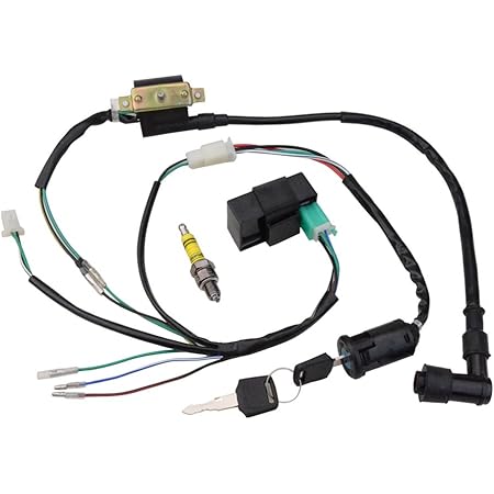


Goofit Ignition Rebuilt Kit Wiring Harness Cdi Spark Plug Replacement For 50cc 70cc 90cc 110cc 125cc Atv Quad Bike Buggy Go Kart Amazon Co Uk Automotive
12 Schematic Diagram Of Motorcycle Cdi Motorcycle Diagram Wiringg Net Kill Switch Motorcycle Wiring Electrical Diagram Cdi Wiring Diagram Kill Switch Motorcycle Wiring Electrical Wiring Diagram Excellent 250cc Chinese Cdi 6 Pin Wiring Diagram The Best Diagram 150cc Wire Pin By H Ruijss On Voertuigen In 21 Electronic Circuit Design Car Alternator Go Kart Frame Pinout diagram of the dc cdi buggy depot technical center ruckus gy6 swap wiring sthus 150cc harness wire loom stator switch electrics assembly for 4 stroke engine Also check kill switch by removing black wire that comes from the CDI Here is a diagram of how the system works Attachments JONWAY Hornet 2 stroke 72 cc BBK #90 main jet 5 gram Sliders 1,500 rpm clutch springs 1,500 rpm contra spring Stock exhaust Performance CDI Koso oversized variator 60 watt Stereo,CD,MP3 player with subwoofer psychedelicode Great


Cdi Wiring Diagram Kill Switch Electrical Diagram Electrical Wiring Diagram
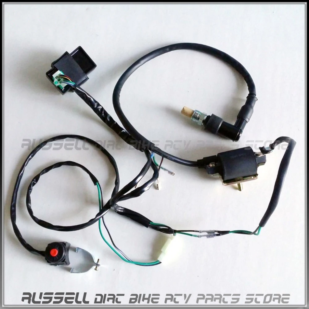


Cdi Ignition Coil Wiring Cable Spark Plug Kill Switch For 90cc 125cc 140cc 150cc Dirt Atv Quad Pit Zongshen
CDI WIRING DIAGRAM AND WIRING DIAGRAM Sunday, Marine Kill Switch Wiring Diagram The switch is a universal variety (for magneto and battery ignition systems) Variety of boat ignition switch wiring diagram Electrical Wiring Diagram Of Motorcycle Electrical Marine products is one of the leading suppliers of wakeboards, water skis, boat parts, and otherWe'll stick our CDI pinout diagram right here so you'll have access to it Please reply and we'll go from there Tao Tao ATF ATV the forum to help me and other trouble shot our carts big thanks cc atv I came across 2 (and a half) tao 's which were not running Plug the CDI back in (kill switch wire dangling) and see if you have spark Ideally this would be 2 volts but many meters KenS999 Hello I have a 05 Sportsman 500 HO and am trying to diagnose a no spark issue Hoping someone could provide a wire color code chart for the ignition system along with electrical specification values, especially the wiring harness coming out of the CDI box I would like to be able to check the condition of stator, coils, regulator etc
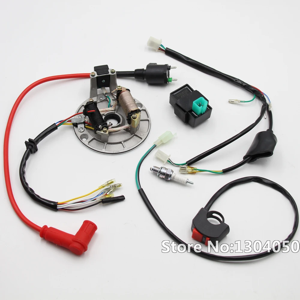


Complete Electrics Magneto Cdi Spark Plug Coil Kill Switch Kick Start Only 50cc 110cc 125cc 150cc Pit Dirt Bikes New Motorbike Ingition Aliexpress


Treats Cdi Party On Tomos A3sp Moped Army
4 Wire Ignition Switch Diagram Atv New Excellent Chinese Cdi Wiring Best Of Kill Switch Electrical Diagram Engineering 5 prong relay wiring diagram wiring diagram is a simplified usual pictorial representation of an electrical circuit it shows the components of the circuit as simplified shapes and the skill and signal links in the middle of the devicesThese two wires areAn ignition kill switch should be hidden or keyoperated A keyoperated, onandoff switch makes concealment unnecessary Many circuits on late model computerized vehicles can be utilized Early model vehicles require that the circuit to the coil be opened to kill the ignition Whichever switch is chosen, it should have a 30amp rating Always


Aftermarket E50 Cdi Kill Switch Wiring Moped Army


Cdi Capacitor Discharge Ignition Circuit Demo Ignition Coil Capacitor Circuit Diagram
The CDI ignition systems, therefore, allow the engine to keep running as long as there is a charge in the power source The block diagram of CDI shown below Construction of Capacitor Discharge Ignition A Capacitor Discharge Ignition consists of several parts and is integrated with the ignition system of a vehicle The foremost parts of a CDIThe higher voltage from the FIREPLUG CDI also exists on the killswitch contacts A switch that is old, or a tether that isn’t being held down as far as it could can cause arcs at upper RPM when the voltage is the highest values, causing a sparkmis With sled running in dark area, open the hood & look for any sparks or arcs from coils, plugcaps, plugwires or any other wiring jumping toKill Switch Four Wheelers Spark Plug Engineering Blue And White New 6 Wire Cdi Wiring Diagram Wiring Diagram Image 6 Wire Cdi Wiring Diagram New 6 Wire Cdi Wiring Diagram 6 Pin Cdi Wiring Diagram Download 5 Pin Cdi Wiring Diagram Suzuki Illustration Wiring Diagram • Hensim atv Wiring Diagram Gallery Danny Autrey cdi diagram Scooter 125 Chinese Atv


Buy Laxeem Full Wiring Harness Loom Kit Cdi Coil Magneto Kick Start Engine For 50cc 70cc 90cc 110cc 125cc Atv Quad Bike Buggy Go Kart Pit Dirt Bikes Online In Turkey B06xz9m4cx


Fancy Scooter Gas Scooters And Electric Scooters Retail And Wholesale
DCCDI counterpart of ACCDI is an ignition analog or digital that uses low voltage external power supply to work the difference ACCDI needs external High Voltage COIL no battery configuration whereas DCCDI needs a battery without HV COIL DCCDI schematic diagram Looking at the picture on the left, it is a complete schematic diagram of a dccdi Its a 4pin system, Ignition Tester for CDI Ignitions Manual RCEXL Mini Tach great for tuning Includes "Y" simple plug and play inline with High Voltage Rcexl ignition CM6 First off, it has to be said that I am big believer in Ignition cut off switches This is a must The RCEXL Opto Gas Engine Kill Switch is one of the most popular switches around When you look at the only connection the batteryNow plenty of guys have asked me to do a video about wiring the kill switch into the wiring for the 49cc 2 stroke engine This is one of the most confusing p


Kill Switch Wiring


Jaguar Cdi Ignition For The Chinese Engine For Bicycles
CDI is equivalent to Capacitor Discharge Ignition and it provides a high level of voltage to sustain the spark plug It can happen at the exact time when igniting the air and fuel mixture as well as powering the boat’s engine When this kill switch stops the engine, it diverts the charge that sets off the spark On smaller boats, it’s connected directly to the outboard motor In largerCdi Motorcycle Diagram Cdi Wiring Diagram Kill Switch Motorcycle Wiring Electrical Wiring Diagram / at Desember 17, 21 Motorcycle wiring diagram, profile picture Cdi motorcycle wiring diagram and jikan annpee complete wiring harness kit wire loom electrics stator coil cdi for atv quad four wheelers cc cc cc go kart dirt The cdi system uses the discharged voltage from the The kill switch and ignition switch on a wiring diagram This time we’re interested in the black with yellow tracer cable It goes from the CDI unit and branches to the ignition switch and to the engine kill switch We coloured this wire red The second interesting cable is the black with white tracer cable


Buy Wiring Loom Kill Switch Ignition Coil Cdi Spark Plug For 110 125 140cc Pit Bike At Affordable Prices Free Shipping Real Reviews With Photos Joom


Buy Cdi Ignition Coil Wiring Loom Kill Switch Sparks Plug Kit For 90cc 110cc 125cc 140cc Scooter Pit Dirt Bike Atv Quad Spark Plug Fordeal
I have replaced the battery, DC cdi, ignition coil, and tried a new stator Still no spark I ran a ground from #4 on cdi to engine And checked the handlebar switches Here are the readings I have Blue / yellow from stator 16 vac Blue /yellow in to cdi from stator 15 vac Cdi in #6 from battery 12vdc Cranking voltage out to coil from Cdi 01vac Wiring Diagrams For Diy Car Repairs, size Literally, a circuit is the course that permits electrical power to flow 5wire CDI bike wiring diagram Pit Bike Wiring Diagram You can save this graphic file to your own laptop Need a wiring diagram!!!!!CDI P/N This switch box replaces these P/N's 1851, A1, , A3, and A5 Warning!
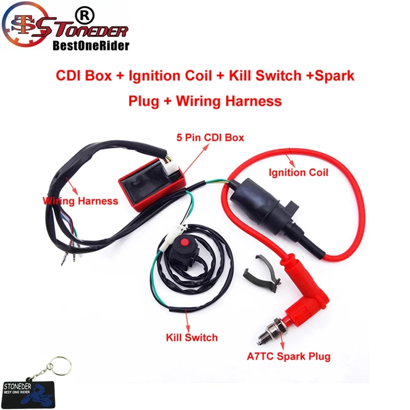


Stoneder Wiring Loom Harness Kill Switch Ignition Coil Ac Cdi Spark Plug 50cc 160 Cc Horizortal Engine Pit Dirt Bike Motorbike Ingition Aliexpress
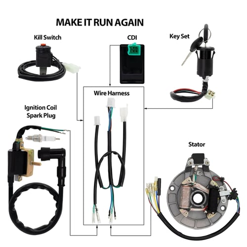


Wiring Harness Loom Ignition Coil Cdi Magneto Stator Ignition Switch Set For 50 140cc Dirt Pit Bike Atv Buy Wiring Harness Loom Ignition Coil Cdi Magneto Stator Ignition Switch Set For 50 140cc
This product is designed for installation by a professional marine mechanic CDI cannot be held liable for injury or damage resulting from improper installation, abuse, neglect or misuse of this product Disconnect the kill wire(s)Cheap oem cdi motorcycle wiring diagram motorcycle part , find complete details Im still not clear on what to do, theres just no wiring diagram out there Connect the blue/green wire from engine to blue/green on cdi and your red wire from the kill switch all togather Diagram,cdi ignition testing,cdi ignition system pdf from motorcycleCdi kill switch diagram Cdi kill switch diagramKawasaki en500 vulcan 500 ltd electrical wiring diagram schematic 1996 09 here On a 4 wire cdi it would be connected to the cdi kill switch should be connected yesno and to the red or the earth wire Researched and submitted by So todays wiring is pretty good Kawasaki er500 er5 er 500 electrical wiring harness diagram


How To Wire A Killswitch Theft Deterrent Youtube


5 Pin Cdi Ignition Coil Kill Switch Wiring For 50cc 110cc 125cc Dirt Bike Ebay
The RCEXL Opto Gas Engine Kill Switch is one of the most popular switches around When you look at the picture of the switch, you will notice there are only 3 cable connectors running out of the unit receiver cable, ignition cable and battery cable connectors Here are the details on the ignition cut off switch 1 This device plugs into a spare receiver channel 2 Includes a remote Push Button Ignition Switch Wiring Diagram New Boat Wiring Kill Switch Small Engine Basic Wiring Customs By Ripper Motorcycle Wiring Harley Shovelhead Harley Bikes On Off Switch Led Rocker Switch Wiring Diagrams Oznium Stereo Amp Car Stereo Stereo Amplifier Wiring Diagrams In 21 Diagram Light Switch Wiring Wire Wonderful 6 Pin Cdi WiringChinese atv Cdi Wiring Diagram Likewise Chinese Cdi 125 Wiring Getting from factor A to direct B


Hobbit Cdi Hardwire Diagram Moped Army
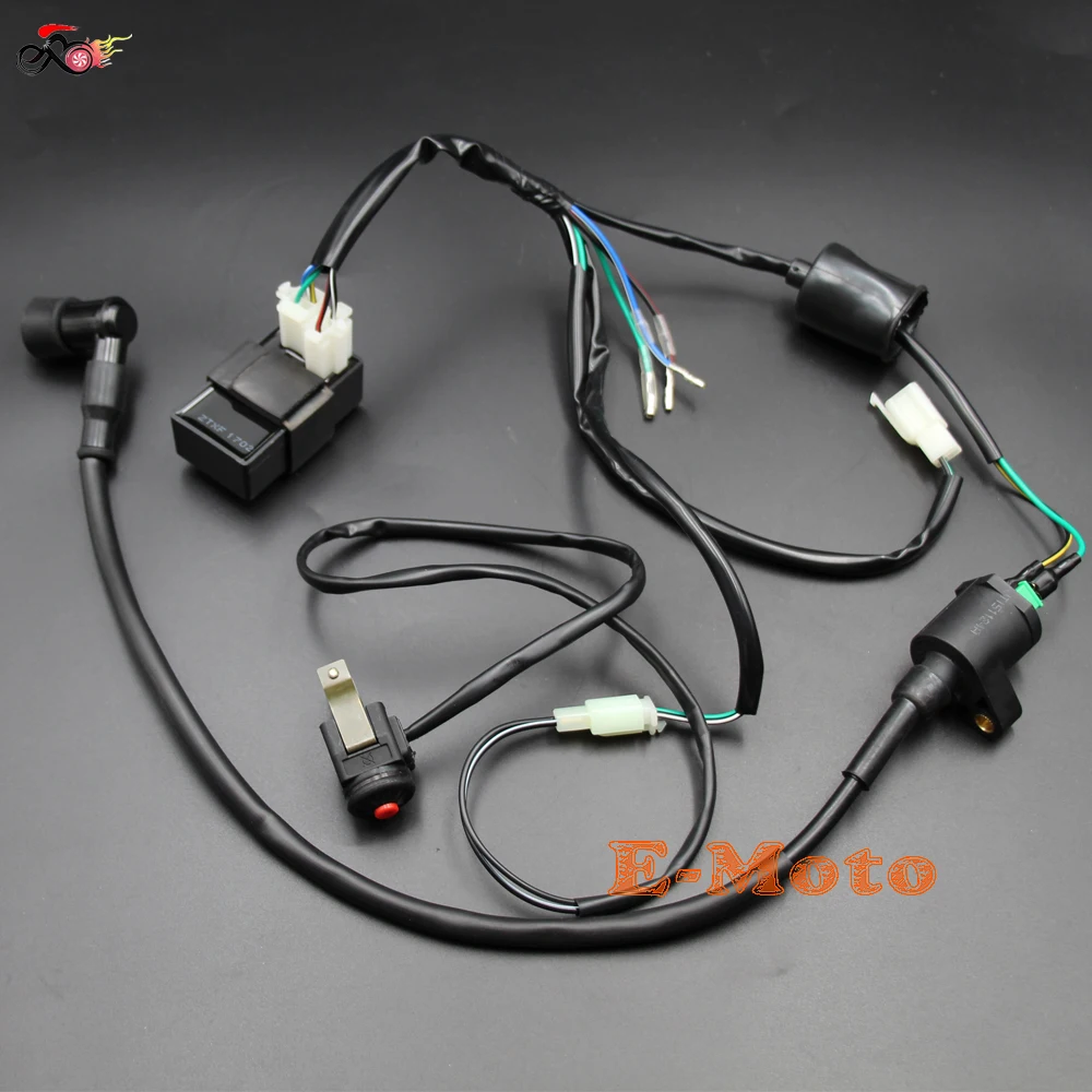


Uzdegimo Ritė Cdi Elektros Laidynas Loom Kill Switch Rinkiniai 50 70 90 110 125 150 160cc Purvo Duobe Dviratį Pirkti Naujas Www Super Shop Lt
Depending on the CDI unit, it should wire up to the stator, the coil, and the kill switch Try to do some searches for a wiring diagram for your bike or a similar model and work backwards from there Also a good time to check all grounds, connections, fuses, andCasoli cdi wiring diagrams spark new racing cdi 6 pin wiring diagram nothin is Sent a pic of the stock wiring diagram There are a few different wiring schematics for the jogzuma Sir i want the buy (real )racing cdi (rpm fast and powerful )can you make one for me ?


Buy Wiring Loom Harness Kill Switch Ignition Coil Cdi Box Spark Plug Rebuild Kit Wwire Diagram Replacement For Kick Start Dirt Pit Bike Atv 50cc 70cc 90cc 110cc 160cc Buggy Go Kart Wire
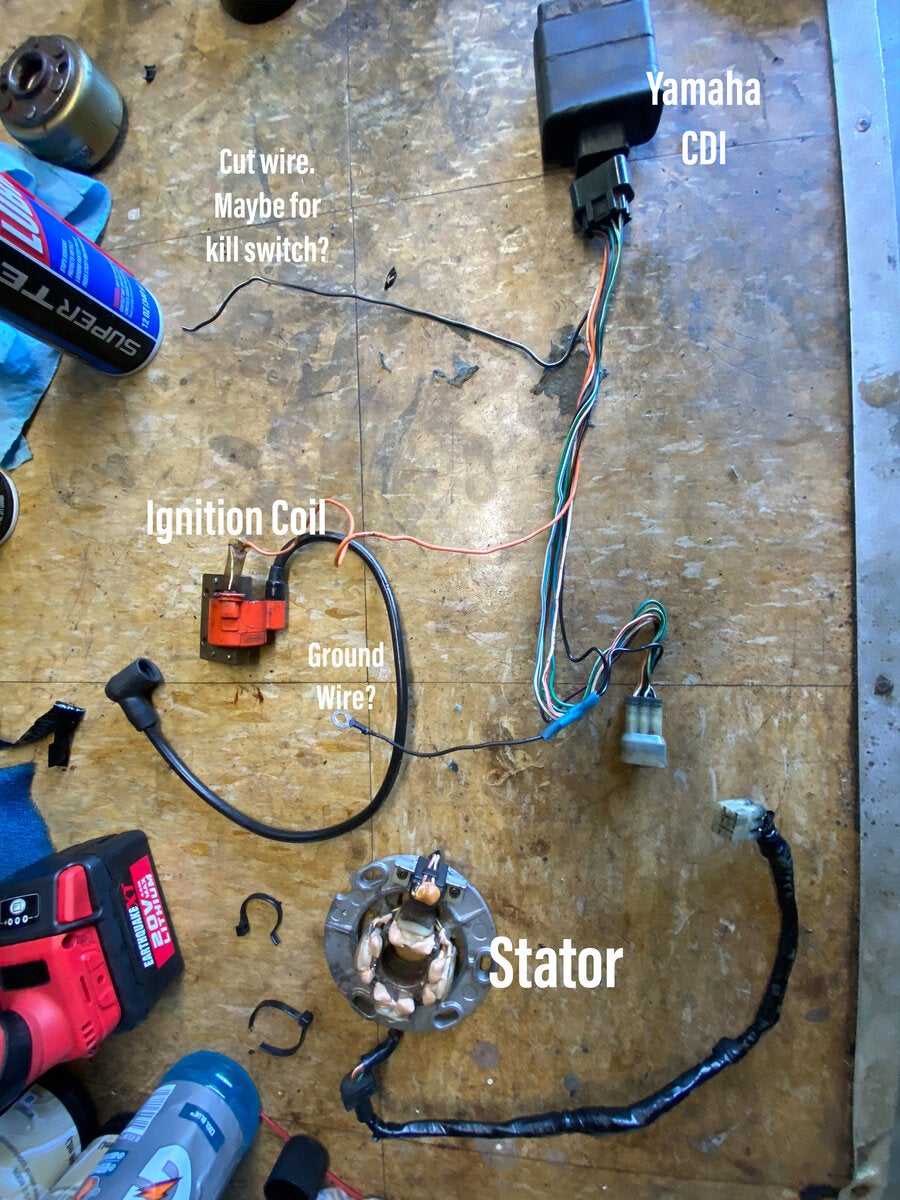


Where To Wire Killswitch Yamaha 2 Stroke Thumpertalk


Elektros Instaliacijos Loom Relės Ritė Lygintuvas Cdi Kill Switch 50cc 70cc 90cc 110cc 125cc Keturratis Quad Bike Buggy Gokart Naujas įvairus Modernus Straipsniai Today


Cdi Motorcycle Wiring Diagram And Jikan Annpee Complete Wiring Harness Kit Wire Loom Electrics Stator Coil Motorcycle Wiring 50cc Dirt Bike Electric Dirt Bike


Dirt Pit Bike Wiring Loom Harness Kill Switch Ignition Coil Cdi 50 110 140 150cc Ebay


Buy Cncmotok Wiring Loom Harness Kill Switch Ignition Coil Cdi Box Spark Plug Rebuild Kit For Kick Start Dirt Pit Bike Atv 50cc 70cc 90cc 110cc 160cc Buggy Go Kart Wire Harness Online


Wiring Loom Light Kill On Off Switch Ignition Coil Cdi Box Spark Plug Kit For 110cc 1cc 125cc Motorcycle Atv Dirtbike Pit Dirt Bike Walmart Canada


Wiring Harness Kill Switch Ignition Coil Cdi For 50 160cc Pit Bike Ssr Thumpstar Ebay


Buy Cdi Ignition Coil Wiring Loom Kill Switch Sparks Plug Kit For 90cc 110cc 125cc 140cc Scooter Pit Dirt Bike Atv Quad Spark Plug Fordeal


Full Electrics 110cc 125cc 140cc Cdi Coil Harness Dirt Bike Atomok Tdr Tdrmoto


Pingel Kill Switch With Dyna Fs Ignition Mod Suzuki Central Forum


Modern Vespa Bajaj Cdi What S The Colour Of The Kill Switch Wire


Buy 5pcs Wiring Loom Kill Switch Coil Cdi Spark Plug Kit For 110cc 125cc 140cc Pit Bike Sha At Affordable Prices Free Shipping Real Reviews With Photos Joom


Kawasaki F7 Kill Switch Install Question Kawasaki Motorcycle Forums
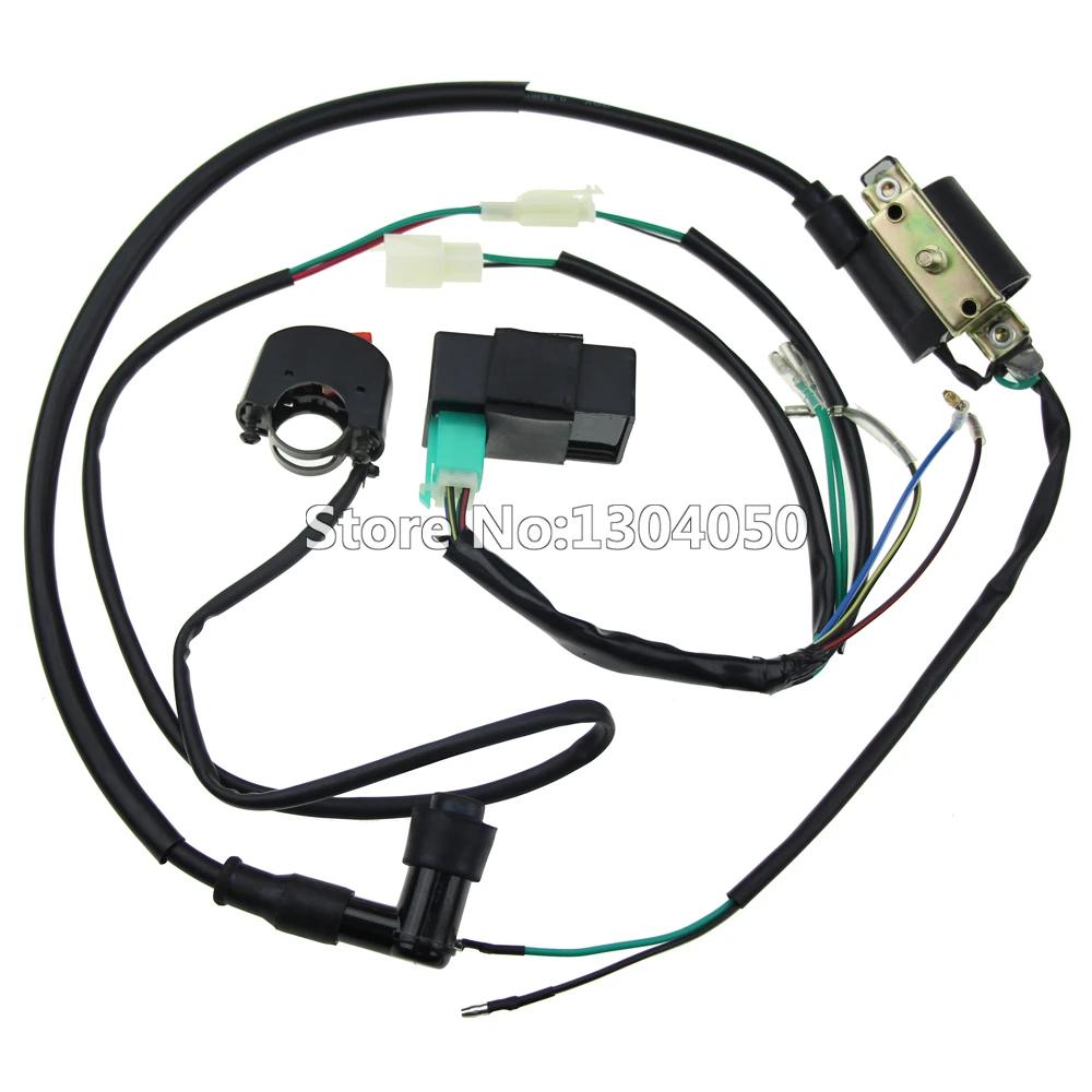


Complete Kick Start Engine Wiring Harness Loom Cdi Box Ignition Coil Kill Switch 50 70 90 110 125 140cc Pitpro Pit Dirt Bike Atv Cdi Box Ignition Coilcdi Ignition Box Aliexpress
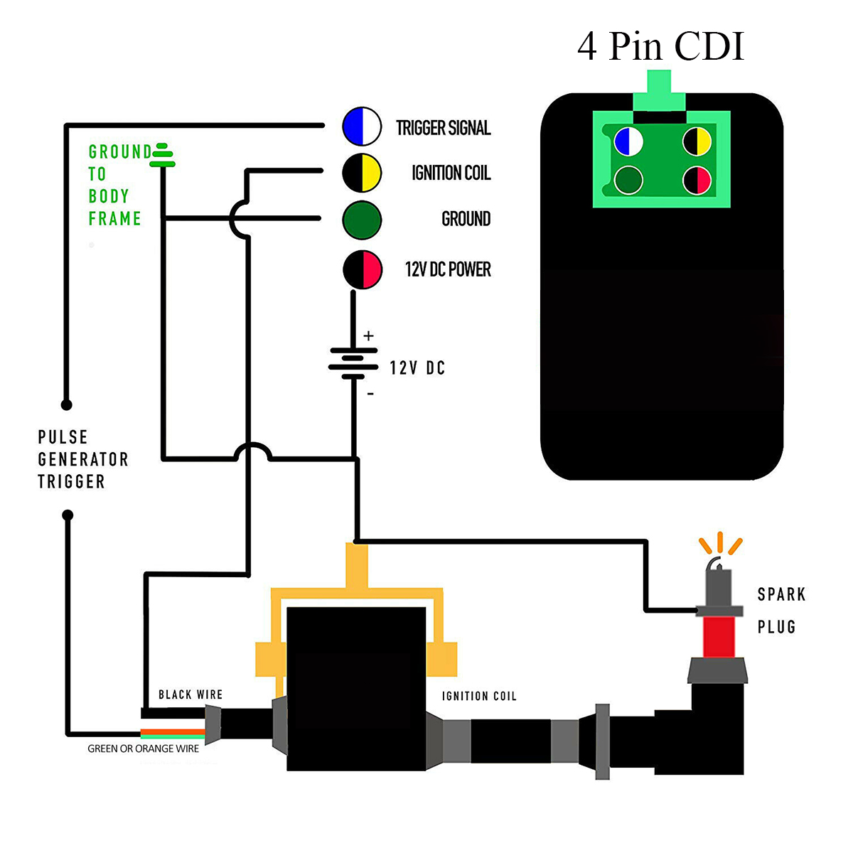


3pcs Dc Cdi Ignition Coil Wiring Loom Harness For Gy6 50 90 110 Cc Go Kart Atv Alexnld Com


Hooper Imports Experts On Chinese Motorcycles And Parts Engines Diagram Kill Switch Engineering
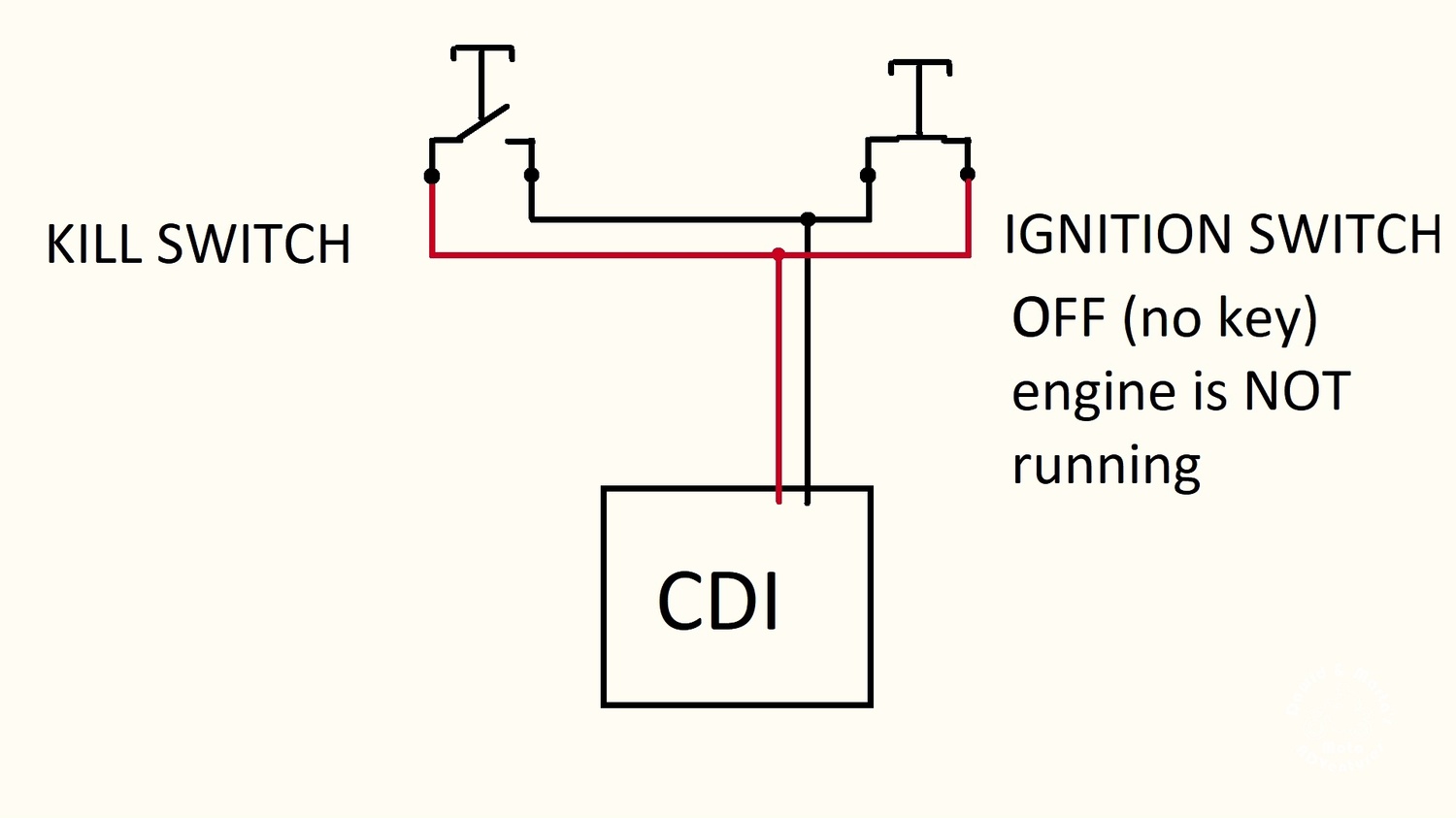


How To Add Ignition Switch To Honda Xr400 Dawid Marta S Moto Adventures


How To Integrate A Cdi Ignition With A Mo Unit Revival Cycles
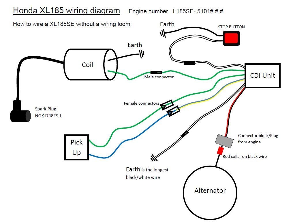


Kill Switch Button Xr Crf80 0 Thumpertalk


Pin By Cheo Aponte On Mecanica In 21 Electronic Circuit Design Car Mechanic Car Alternator


Excellent 250cc Chinese Cdi 6 Pin Wiring Diagram The Best Diagram Wire 150cc


Need Help Wiring Remote Shut Off Atvconnection Com Atv Enthusiast Community
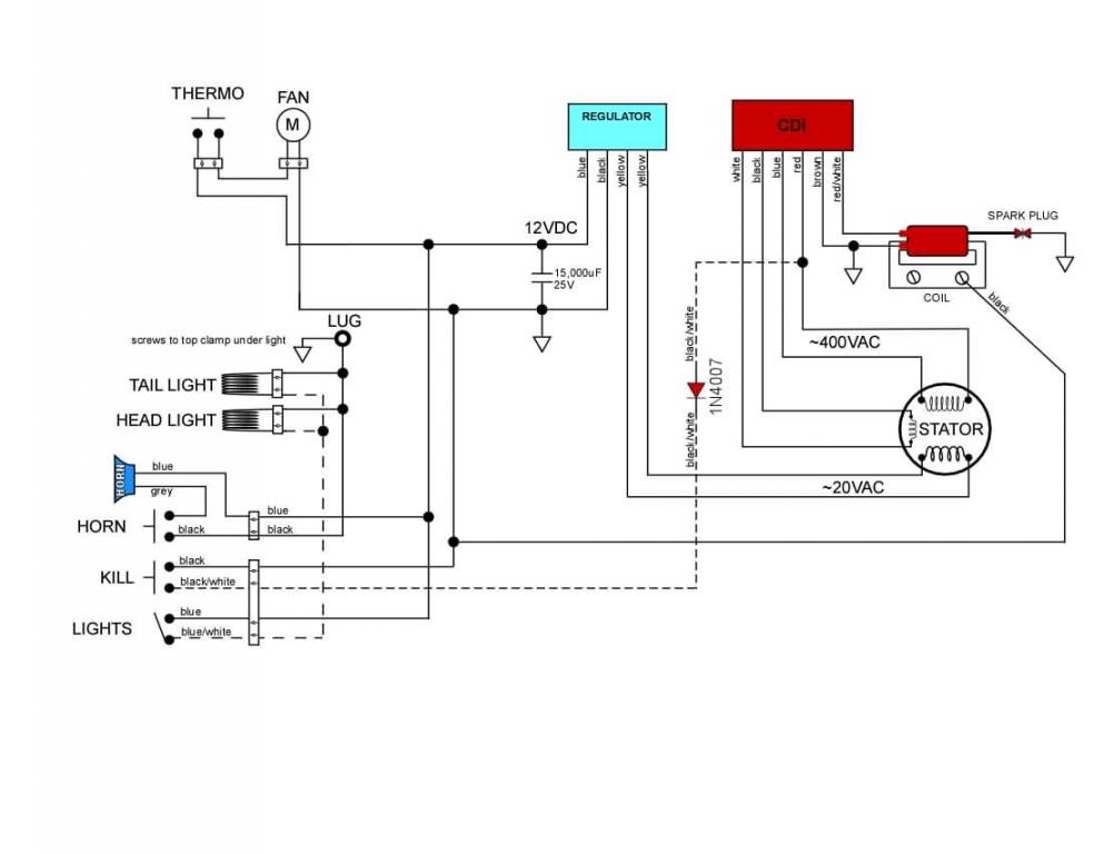


My 08 Rev3 250 Doesnt Have A Kill Switch Help Please Beta Trials Central
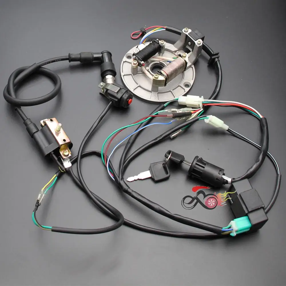


Ispardavimas Ateityje Pradėti Laidynas Cdi Statoriaus Uzdegimo Ritė Kill Switch Zvake 50cc 70cc 110cc 125cc Purvo Duobe Dviratį Sdg Coolster Klx Centras D Statyba Lt
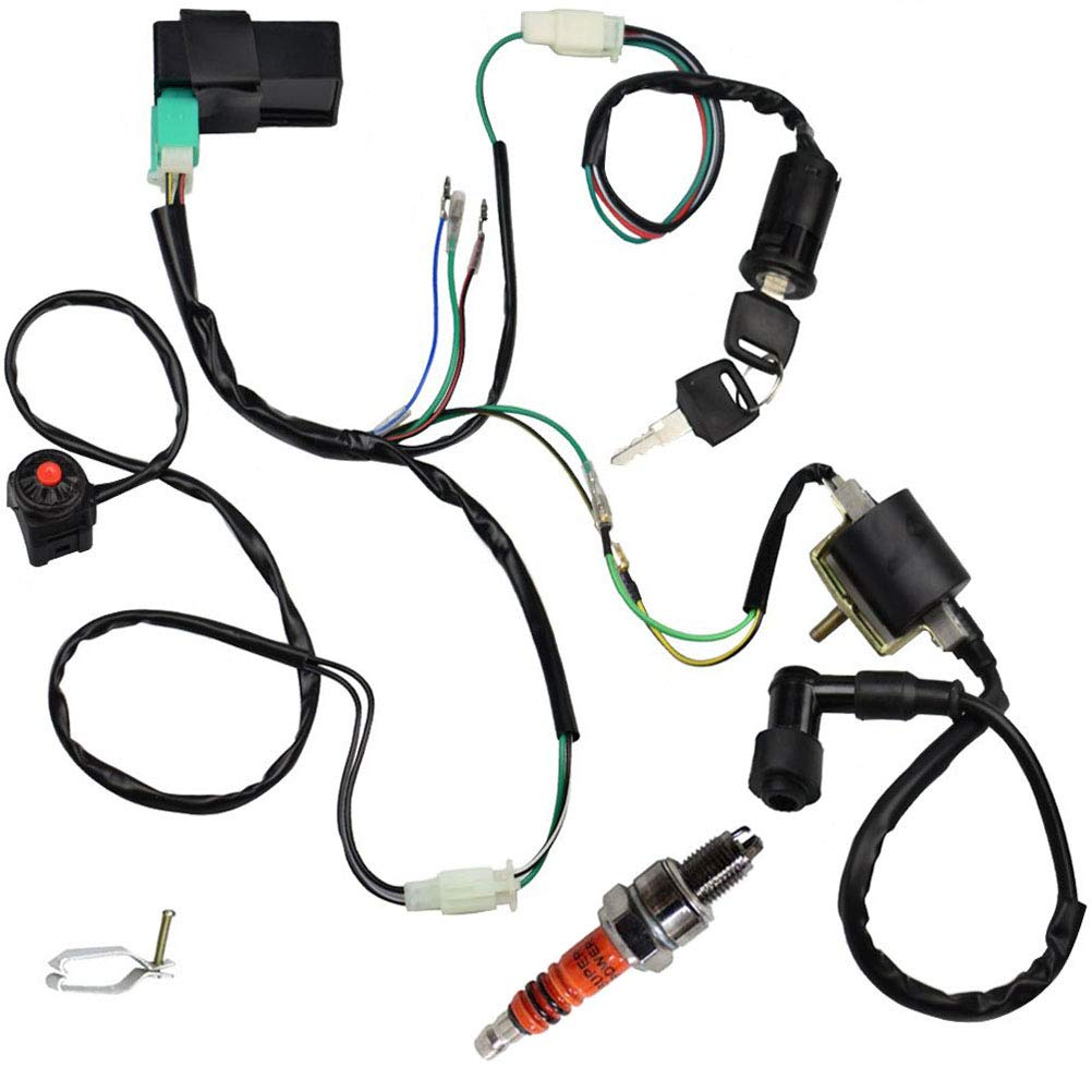


Wire Harness Wiring Loom Cdi Ignition Coil Kill Switch Spark Plug Rebuild Kit For 125cc 110cc 90cc 70cc 50cc Atv Go Kart Kick Start Dirt Bike Pit Bike Quad Bike By Topemai


Cdi Wiring Diagram Kill Switch Motorcycle Wiring Electrical Wiring Diagram


Kill Switch Motorcycle Wiring Diagram


Motorized Bicycle Kill Switch Wiring Guide Motored Bikes Motorized Bicycle Forum


Kill Switch On Ac Vs Dc Cdi Scooter Professor


How Do Dirt Bike Kill Switch Work Troubleshooting Guide Atvfixed Com


Wiring Puch Cdi Questions Moped Army


Kill Switch Wiring Motored Bikes Motorized Bicycle Forum


How Do Dirt Bike Kill Switch Work Troubleshooting Guide Atvfixed Com


130 50cc Moped Ideas 50cc Moped 50cc Scooter


Longblock Box End Wrench Diagram Ignite
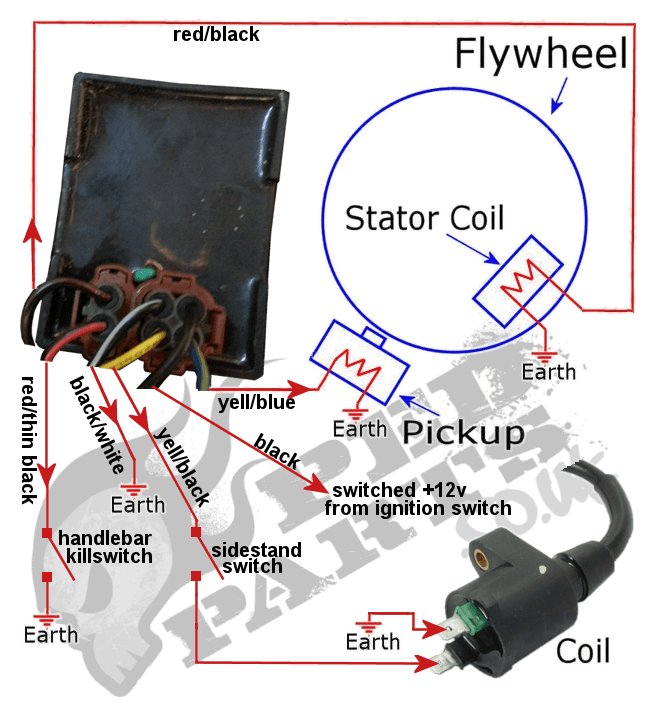


Fault Finding Peugeot V Clic Cdi Blog Pedparts Uk


Motobecane Cdi Ignition Le Partie Ground Confusion Moped Army


Amazon Com Jcmoto Full Wiring Harness Loom Kit Cdi Coil Magneto Kick Start Engine For 50cc 70cc 90cc 110cc 125cc Atv Quad Bike Buggy Go Kart Pit Dirt Bikes Automotive
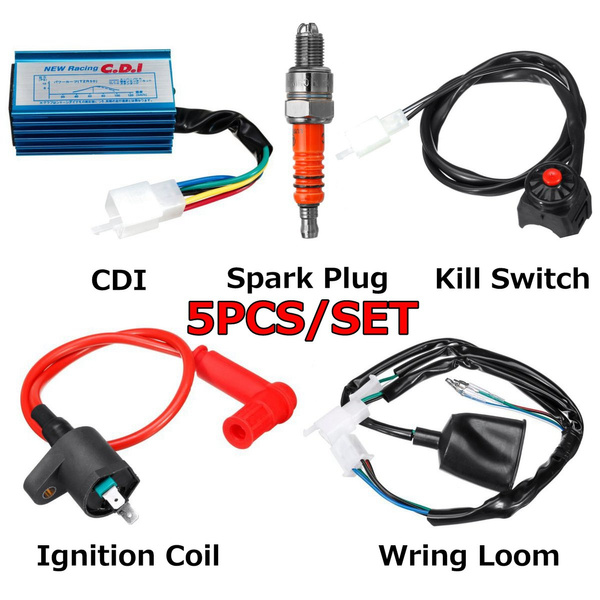


5pcs 4pcs Set Racing Cdi Ignition Coil Kill Switch Wiring Loom Kit For 50cc 70cc 110cc 125cc 140cc 150cc Atvs Scooter Kick Start Dirt Bikes Wish


Amazon Com Jcmoto Full Wiring Harness Loom Kit Cdi Coil Magneto Kick Start Engine For 50cc 70cc 90cc 110cc 125cc Atv Quad Bike Buggy Go Kart Pit Dirt Bikes Automotive


3
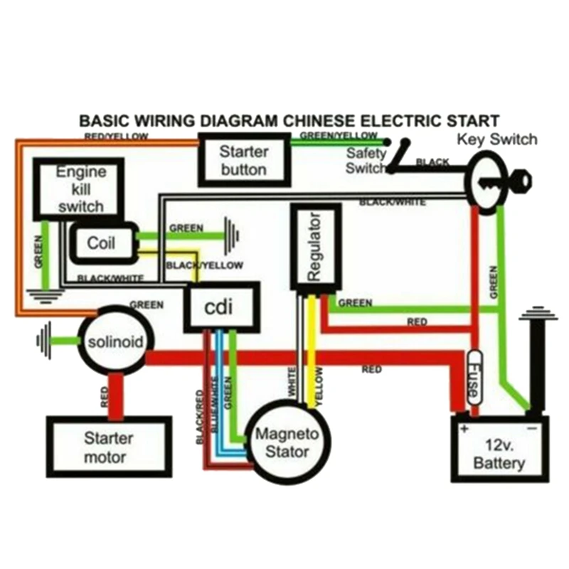


Cdi Ignition Coil Wiring Harness Switch Stator Solenoid Relay Regulator For Atv Quad 150cc 0cc 250cc 300cc Dirt Bike Aliexpress Automobiles Motorcycles


Chinese Gy6 Wiring Diagram Schema Wiring Diagram Gy6 Cdi Wiring Diagram Wiring Diagram Diagram Wire 150cc


Kill Switch Wiring


Racing Cdi Ignition Coil Kill Switch Wiring Loom Harness For 50 160cc Pit Bike Ebay


1


Need Wiring Diagram Installed Hughs Handbuilt Cdi Yamaha Xs650 Forum


Wiring Loom Coil Cdi 110cc 125cc 140cc Kick Start Dirt Pit Bike Atomik Tdrmoto


How To Wire A Motorcycle Basic Wiring Diagrams Motorcyclezombies Com
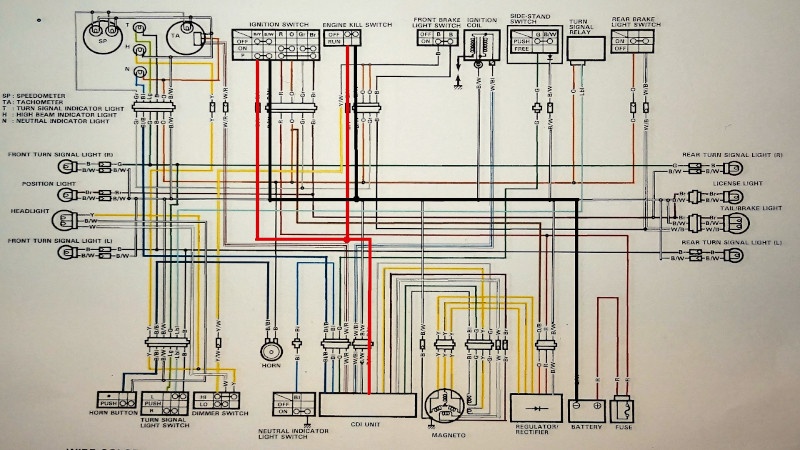


No Spark Issue Kill Switch And Ingition Switch Test Dr350 Rebuild Dawid Marta S Moto Adventures
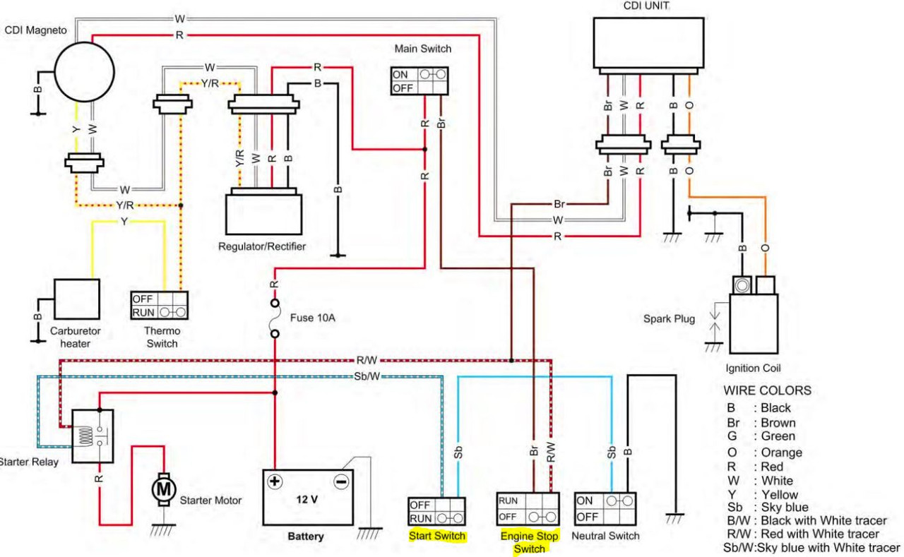


Teton Gravity Research Forums
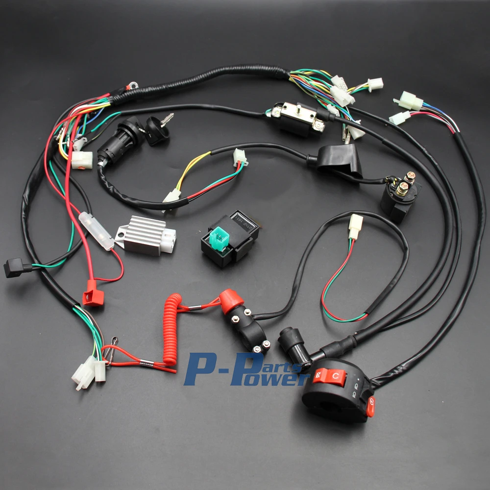


Wiring Harness Loom Solenoid Coil Rectifier Cdi Kill Switch 50cc 70cc 90cc 110cc 125cc Atv Quad Bike Buggy Gokart New Coil Cdi 125cc Quad Atv50cc Cdi Aliexpress
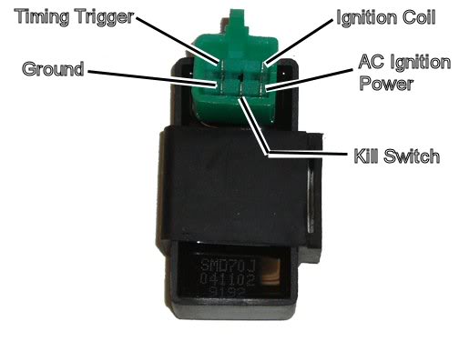


5 Pin Cdi Kill Switch Information Needed Atvconnection Com Atv Enthusiast Community
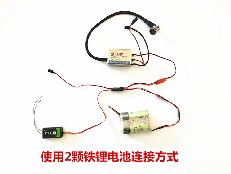


Cdi Remote Flameout Switch Rc Engine Flameout Kill Switch For Dle Gasoline Engine Buy Cdi Remote Flameout Switch Rc Engine Flameout Kill Switch Kill Switch For Dle Gasoline Engine Product On Alibaba Com


How Do Dirt Bike Kill Switch Work Troubleshooting Guide Atvfixed Com


Puch Cdi Version 2 Kill Switch Wiring Imgur


1
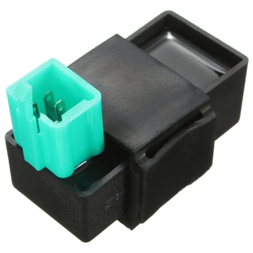


Wiring Loom Kill Switch Coil Cdi Plug For 110cc 125cc 140cc Pit Bike Buy Wiring Loom Kill Switch Coil Cdi Plug For 110cc 125cc 140cc Pit Bike Prices Reviews Zoodmall
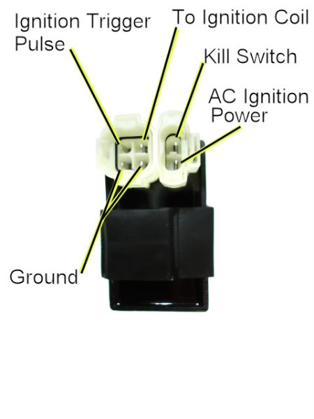


More Info Needed On 6pin Cdi Kill Switch Pin Atvconnection Com Atv Enthusiast Community


5 Pin Cdi Wiring Diagram Mediapickle Diagram Electrical Diagram Wire
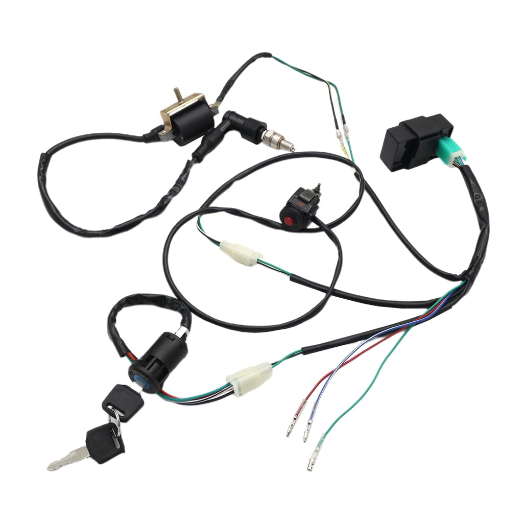


Ignition Coil Wiring Loom Harness Kill Switch Cdi For 50cc 160cc Pit Dirt Bike Walmart Canada


Elektros Instaliacijos Loom Relės Ritė Lygintuvas Cdi Kill Switch 50cc 70cc 90cc 110cc 125cc Keturratis Quad Bike Buggy Gokart Naujas Ispardavimas Nuolaidos Www Socialretex Lt
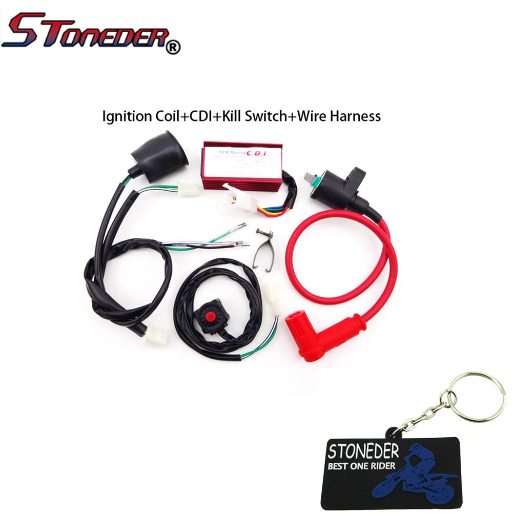


Stoneder Racing Ignition Coil Ac Cdi Box Wiring Loom Harness Kill Switch For 50 160cc Pit Dirt Bike Buy At A Low Prices On Joom E Commerce Platform
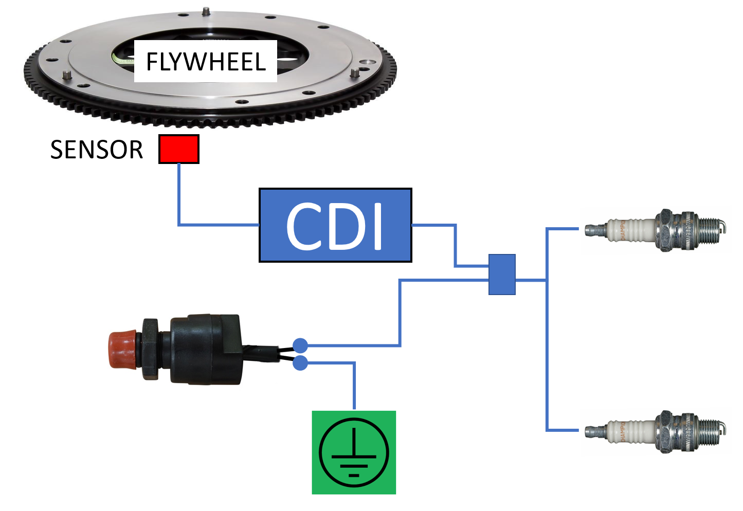


How To Fit A Kill Switch Boat Fittings


Simple Motorcycle
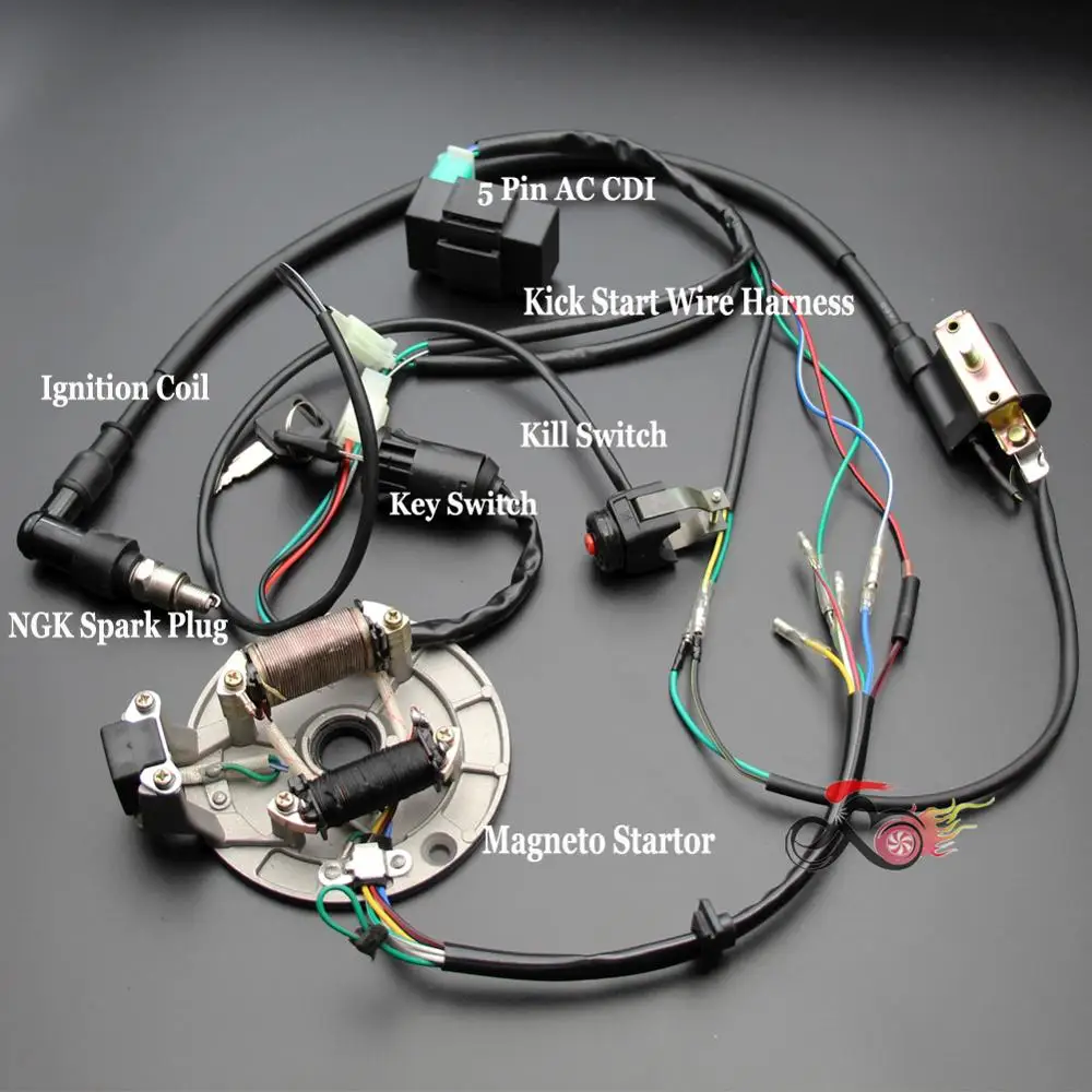


Ispardavimas Ateityje Pradėti Laidynas Cdi Statoriaus Uzdegimo Ritė Kill Switch Zvake 50cc 70cc 110cc 125cc Purvo Duobe Dviratį Sdg Coolster Klx Pardavimas Www Sakarmakar Lt
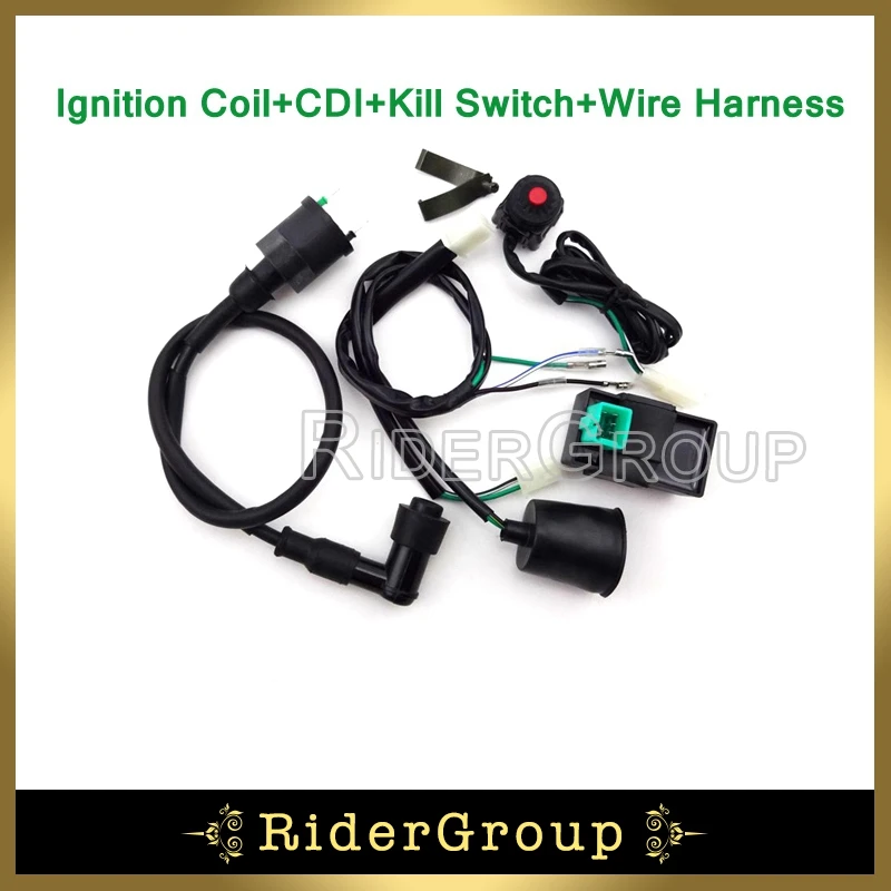


Pit Dirt Bike Wiring Loom Harness Kill Switch Ignition Coil Ac Cdi For 50 70 90 110 125 140 150 160 Cc Engine Chinese Ac Cdi Ignition Coil160 Cc Aliexpress


Wiring Diagram


Motorized Bicycle Kill Switch Wiring Guide Motored Bikes Motorized Bicycle Forum


Rc Kill Switch


Buy Cncmotok Wiring Loom Harness Kill Switch Ignition Coil Cdi Box Spark Plug Rebuild Kit For Kick Start Dirt Pit Bike Atv 50cc 70cc 90cc 110cc 160cc Buggy Go Kart Wire Harness Online
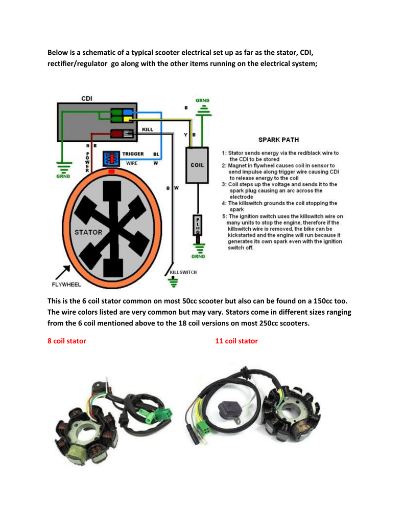


Below Is A Schematic Of A Typical Scooter Electrical Set Up As Far As
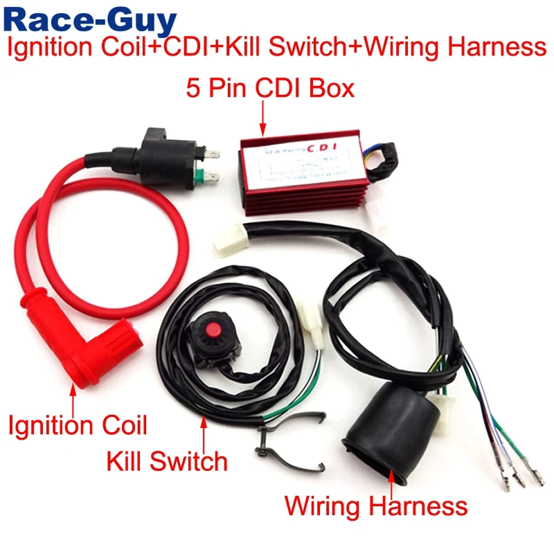


Racing Ignition Coil 5 Pin Ac Cdi Box Wiring Loom Harness Kill Switch For 50cc 70cc 90cc 110cc 125cc 140cc 150cc 160cc Eng Aliexpress


All Electrics 50cc 70cc 110cc 125cc 140cc Wire Harness Cdi Coil Dirt Bike Engine


Pit Dirt Bike Cdi Ignition Coil Kill Switch Wiring Harn 110cc 140cc Taotao Lifan Ebay


Buy Pit Bike Wiring Harness Wiring Loom Harness Kill Switch Ignition Coil Cdi Box Spark Plug Rebuild Kit For 50cc 70cc 90cc 110cc 160cc Kick Start Dirt Pit Bike Atv Buggy Go Kart Wire
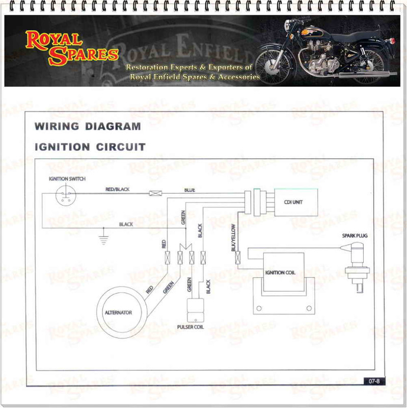


Bullet A350 Machismo Kill Switch Issue


No comments:
Post a Comment